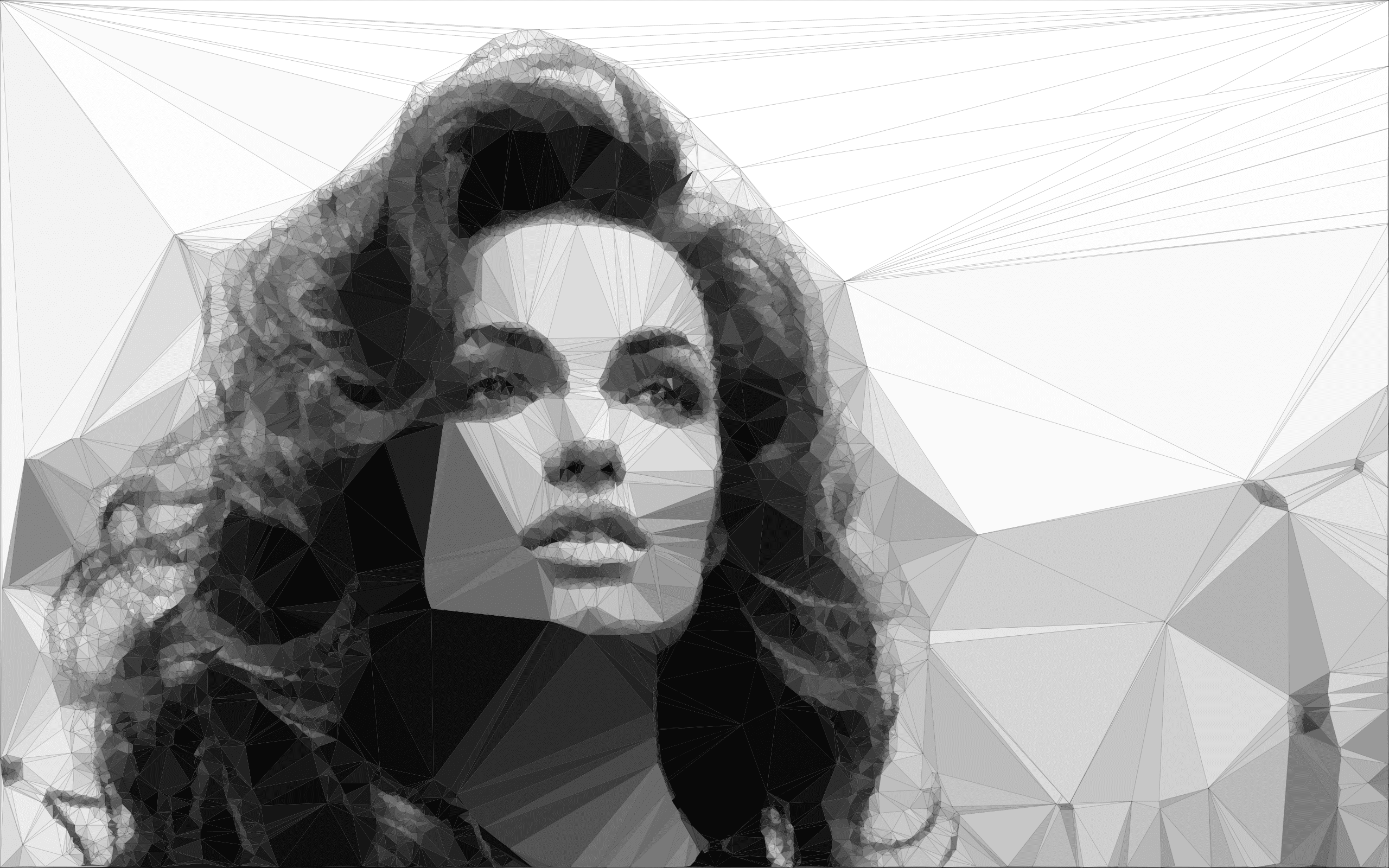
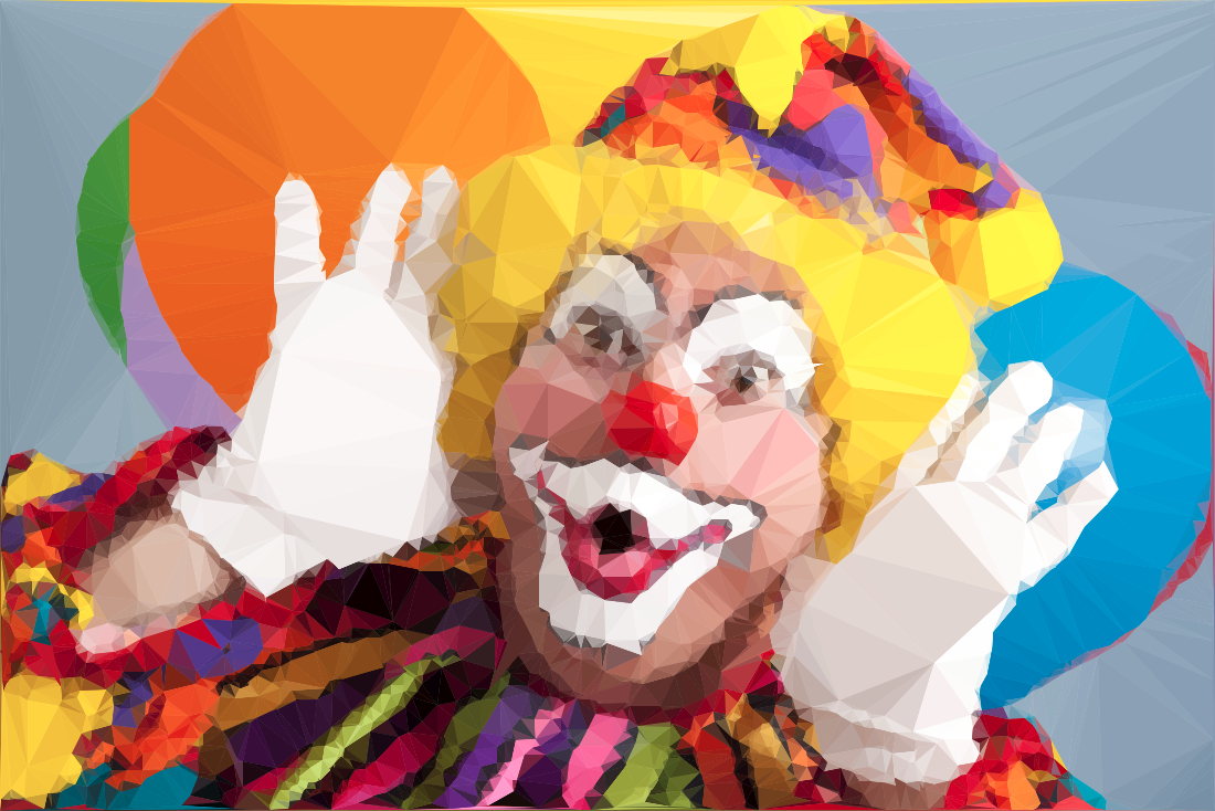
In this article we present a technique to triangulate source images, converting them to abstract, someway artistic images composed of tiles of triangles. This will be an attempt to explore the fields between computer technology and art.
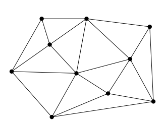
But first, what is triangulation? Simply spoken a triangulation partitions a polygon into triangles which allows, for instance, to compute the area of a polygon and make some operations on the computed polygon surface, for example to interpolate the triangulated area color palette and repaint it with the obtained average color. In other terms the triangulation might be concepted as a geometric object defined by a point set, but what differentiates the polygons from a point set is the latter does not have an interior, except if we treat the point set as a convex hull/polygon. But to think of a point set as a convex polygon, the points from the interior of the convex hull should not be ignored completely. This is what differentiates the Delaunay triangulation from the other triangulation techniques.
Delaunay Triangulation
Wikipedia has a very succinct definition of the Delaunay triangulation:
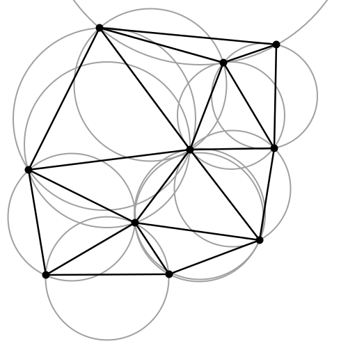
“… a Delaunay triangulation (also known as a Delone triangulation) for a given set P of discrete points in a plane is a triangulation DT(P) such that no point in P is inside the circumcircle of any triangle in DT(P)” ( https://en.wikipedia.org/wiki/Delaunay_triangulation ). What does this mean?
The circumcircle of a triangle is the unique circle passing through all the vertices of the triangle. This will get valuable meaning in the following. So considering that we have a set of six points we can obtain a triangulated polygon by tracing a circle around each vertex of the constructed triangle in such a manner that the circumcircle of all five triangles are empty. We also say, that the triangles satisfy the empty circle property (Fig.2).
After this short theoretical introduction now we want to apply this technique to a more practical but at the same time aesthetical field, concretely to transform an input image to it’s triangulated counterpart. Having the basic idea and it’s theoretical background we can start to construct the basic building blocks of the algorithm.
Above all a first notice: we will use Go as programming language. First, because it has a very clean and easy to use API, second because of its sheer power and last but not least, because Go as a programming language is getting more and more attraction. Unfortunately the language is still used by little in the graphics programming or image processing field. So this will be a good opportunity to demonstrate how well suited is the language for this kind of projects.
The Algorithm
Now into the algorithm. As the basic components are triangles we define a Triangle structs, having as constituents the nodes, it’s edges and the circumcircle which describes the triangle circumference.
[code lang=”go”]type Triangle struct {
Nodes []Node
edges []edge
circle circle
}[/code]
Next we create a circumscribed circle of this triangle. The circumcircle of a triangle is the circle which has the three vertices of the triangle lying on its circumference. Once we have the circle center point we can calculate the distance between the node points and the triangle circumcircle. Then we can calculate the circle radius.
We can transpose this in the following Go code:
[code lang=”go”]
// newTriangle creates a new triangle which circumcircle encloses the point to be added.
func (t Triangle) newTriangle(p0, p1, p2 Node) Triangle {
t.Nodes = []Node{p0, p1, p2}
t.edges = []edge{{newEdge(p0, p1)}, {newEdge(p1, p2)}, {newEdge(p2, p0)}}
circle := t.circle
ax, ay := p1.X-p0.X, p1.Y-p0.Y
bx, by := p2.X-p0.X, p2.Y-p0.Y
m := p1.X*p1.X – p0.X*p0.X + p1.Y*p1.Y – p0.Y*p0.Y
u := p2.X*p2.X – p0.X*p0.X + p2.Y*p2.Y – p0.Y*p0.Y
s := 1.0 / (2.0 * (float64(ax*by) – float64(ay*bx)))
circle.x = int(float64((p2.Y-p0.Y)*m+(p0.Y-p1.Y)*u) * s)
circle.y = int(float64((p0.X-p2.X)*m+(p1.X-p0.X)*u) * s)
// Calculate the distance between the node points and the triangle circumcircle.
dx := p0.X – circle.x
dy := p0.Y – circle.y
// Calculate the circle radius.
circle.radius = dx*dx + dy*dy
t.circle = circle
return t
}[/code]
The question is how we get the triangle points from the input image? To obtain a large triangle distribution on the image parts with more details we need somehow to analyze the image and mark the sensitive information. How we do that? Sobel filter operator on the resque. The Sobel operator is used in image processing to detect image edges. It’s working with an energy distribution matrix to differentiate the sensitive image informations from the less sensitive ones.
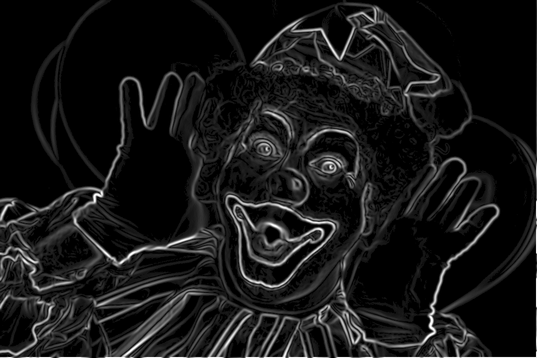
Once we obtained the sobel image we can sparse the triangle points randomly by applying some threshold value. At the end we obtain an array of randomly distributed points, but these points are more dense on the sensitive image parts, and scarce on less sensitive ones.
Once we have the edge points we check whether the points are inside the triangle circumcircle or not. We save the triangle edges in case they are included and carry over it they are not. Then in a loop we search for (almost) identical edges and remove them.
[code lang=”go”]
// Insert will insert new triangles into the triangles slice.
func (d *Delaunay) Insert(points []Point) *Delaunay {
var (
i, j, k int
x, y, dx, dy int
distSq int
polygon []edge
edges []edge
temps []Triangle
)
for k = 0; k < len(points); k++ {
x = points[k].x
y = points[k].y
triangles := d.triangles
edges = nil
temps = nil
for i = 0; i < len(d.triangles); i++ {
t := triangles[i]
//Check whether the points are inside the triangle circumcircle.
circle := t.circle
dx = circle.x – x
dy = circle.y – y
distSq = dx*dx + dy*dy
if distSq < circle.radius {
// Save triangle edges in case they are included.
edges = append(edges, t.edges[0], t.edges[1], t.edges[2])
} else {
// If not included carry over.
temps = append(temps, t)
}
}
polygon = nil
// Check duplication of edges, delete if duplicates.
edgesLoop:
for i = 0; i < len(edges); i++ {
edge := edges[i]
for j = 0; < len(polygon); j++ {
// Remove identical edges.
if edge.isEq(polygon[j]) {
// Remove polygon from the polygon slice.
polygon = append(polygon[:j], polygon[j+1:]…)
continue edgesLoop
}
}
// Insert new edge into the polygon slice.
polygon = append(polygon, edge)
}
for i = 0; i < len(polygon); i++ {
edge := polygon[i]
temps = append(temps, t.newTriangle(edge.nodes[0], edge.nodes[1], newNode(x, y)))
}
d.triangles = temps
}
return d
}[/code]
Now that we have the nodes, in order to construct the triangulated image, the last thing we need to do is actually to draw the lines between nodes points by applying the underlying image pixel colors. The way we can achieve this is to loop over all the nodes and connect each edge point.
[code lang=”go”]
triangles := delaunay.Init(width, height).Insert(points).GetTriangles()
for _, t := range triangles {
p0, p1, p2 := t.Nodes[0], t.Nodes[1], t.Nodes[2]
ctx.Push()
ctx.MoveTo(float64(p0.X), float64(p0.Y))
ctx.LineTo(float64(p1.X), float64(p1.Y))
ctx.LineTo(float64(p2.X), float64(p2.Y))
ctx.LineTo(float64(p0.X), float64(p0.Y))
cx := float64(p0.X+p1.X+p2.X) * 0.33333
cy := float64(p0.Y+p1.Y+p2.Y) * 0.33333
j := ((int(cx) | 0) + (int(cy) | 0)*width) * 4
r, g, b := srcImg.Pix[j], srcImg.Pix[j+1], srcImg.Pix[j+2]
ctx.SetFillStyle(gg.NewSolidPattern(color.RGBA{R: r, G: g, B: b, A: 255}))
ctx.FillPreserve()
ctx.Fill()
ctx.Pop()
}
[/code]
By tweaking the parameters we can obtain different kind of results. We can draw only the line strokes, we can apply different threshold values to filter out some edges, we can scale up or down the triangle sizes by defining the maximum point limit, we can export only to grayscale mode etc. The possibilities are endless.
Using Go Interfaces
By default, the output is saved to an image file, but using interfaces, the Go way to achieve polymorphism, we can export even to a vector format. This is a nice touch considering that using a small image as input element we can export the result even to an svg file, which lately can be scaled up infinitely without image loss and consuming very low processing footprint.
The only thing we need to do is to declare an interface having a single method signature. This needs to be satisfied by each struct type implementing this method.
[code lang=”go”]
// Drawer interface defines the Draw method.
// This has to be implemented by every struct which declares a Draw method.
// Using this method the image can be triangulated as raster type or SVG.
type Drawer interface {
Draw(io.Reader, io.Writer) ([]Triangle, []Point, error)
}
[/code]
In our case we need two struct types, both of them implementing the same method differently. For example, we could have an image struct type declared in the following way:
[code lang=”go”]
p := &triangle.Processor{
BlurRadius: *blurRadius,
SobelThreshold: *sobelThreshold,
PointsThreshold: *pointsThreshold,
MaxPoints: *maxPoints,
Wireframe: *wireframe,
Noise: *noise,
StrokeWidth: *strokeWidth,
IsSolid: *isSolid,
Grayscale: *grayscale,
OutputToSVG: *outputToSVG,
OutputInWeb: *outputInWeb,
}
img := &triangle.Image{*p}
[/code]
and another svg one declared as:
[code lang=”go”]
svg := &triangle.SVG{
Title: "Delaunay image triangulator",
Lines: []triangle.Line{},
Description: "Convert images to computer generated art using delaunay triangulation.",
StrokeWidth: p.StrokeWidth,
StrokeLineCap: "round", //butt, round, square
Processor: *p,
}
[/code]
Each of them will implement the same Draw method differently
Expose the algorithm as an API endpoint
Having a good system architecture, coupled with Go blazing fast execution time and goroutines (another feature of the Go language to parallelize the execution) the algorithm can be exposed to an API endpoint in order to process a large amount of images and then make it accessible through a web application.
What could be a real use case of this technique? Well one of the many possibilities would be to create abstract, artistic images from the source images. Exporting to an svg file, the output lately can be imported to vector graphics programs, like Adobe Illustrator and can be even further manipulated to create custom vector illustrations, huge mashes etc. So the possibilities are endless.
Conclusion
At Filestack, we are always looking at advancements in image processing to deliver engaging experiences for our customers. This is the first among a series of articles that will highlight some pretty interesting image processing techniques. If there is something that you’d like for us to dive deeper into, please do let us know below.
Filestack is a dynamic team dedicated to revolutionizing file uploads and management for web and mobile applications. Our user-friendly API seamlessly integrates with major cloud services, offering developers a reliable and efficient file handling experience.
Read More →
